RF Profiler User Guide

Show Path Profile Button
The area contains three views, Path Profile, Data Values, and Map.
-
1.Path Profile View
-
This view shows the loaded terrain data at the selected datapoint accuracy selected. 100% or 60% Fresnel Zone and ground cover will display, depending on selections set on the main page
-
This view is interaction, allowing pan and zoom operations. It is also mapped with the slider function in area 2. When the slider or a distance is entered, the red bar will move to match the location on terrain data.
-
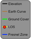
Black Line - Elevation
-
Brown Line - Earth Curvature
-
Green Line - Ground Cover
-
Yellow Line - Line of Sight
-
Blue Line - Fresnel Zone, 60% or 100%
-
Snapshot Button - Takes a snapshot of the path exactly as shown. Snapshot will be used in email and print operation.
-
IMPORTANT. A snapshot must be taken before any image can be emailed or printed.
2. Data Values and Slider operation View
-
This area uses a slider or data entry to select a specific location in the link path. Both the Path Profile View and Map view will move to match the distance setting entered.
-
Clearance values are shown from the Line of Sight path and Fresnel Zone to ground cover and to ground (including earth curvature) and the given location.
3. Map View
-
This view is interaction, allowing pan and zoom operations. It is also mapped with the slider function in section 2. When the slider or a distance is entered, the mid-point pin will move to the match location on the map. This allows zooming in to view arial images of terrain, building, and other object with may obstruct the RF Path.